
Abstract
An electrical power source is essential for the operation of most electronic equipment. Some portable equipment such as radio receivers and pocket calculators may be battery operated, but most electronic equipment requires an electrical supply. In this chapter, we examine the operation and design of linear power supplies that convert an AC voltage from the public mains supply into a stable DC voltage. At the end of the chapter, the student will be able to:
Access this chapter
Tax calculation will be finalised at checkout
Purchases are for personal use only
Bibliography
J. Millman, C.C. Halkias, Integrated Electronics: Analog and Digital Circuits and Systems (Mc Graw Hill Book Company, New York, 1972)
R. Coughlin, F. Driscoll, Operational Amplifiers and Linear Integrated Circuits, 5th edn. (Prentice Hall, New Jersey, 1998)
Author information
Authors and Affiliations
Problems
Problems
-
1.
Describe the operation of a full-wave rectifier and derive the expression for the average and rms output voltages.
-
2.
Explain how the inclusion of a filter capacitor reduces the ripple in the output voltage and derive an expression for the peak-to-peak value of this ripple voltage.
-
3.
Design an unregulated power supply to deliver 15 volts at 1 ampere. Use a 15 volt transformer with a bridge rectifier and allow for a maximum ripple voltage of 1.5 volts peak-to-peak.
-
4.
Re-design the circuit of Question 3 using a half-wave rectifier.
-
5.
A voltage from an unregulated supply varies between a minimum value of 12 volts and a maximum value of 18 volts. Using this unregulated supply, design a Zener-regulated supply that delivers 9 volts DC with a current capacity of 15 mA.
-
6.
Design a single transistor regulated supply using a Zener diode capable of delivering 15 V at 120 mA. Use a half-wave rectifier to drive the regulator. Show how this circuit can be equipped with short-circuit protection.
-
7.
Design a regulated supply using a Darlington pair and a Zener diode that delivers 9 V at 1.5 A. Use a full-wave rectifier to drive the regulator.
-
8.
Explain the operation of the regulator shown in Fig. 10.66. Using this circuit, design a regulated supply to deliver 9 volts at 0.5 A
Fig. 10.66 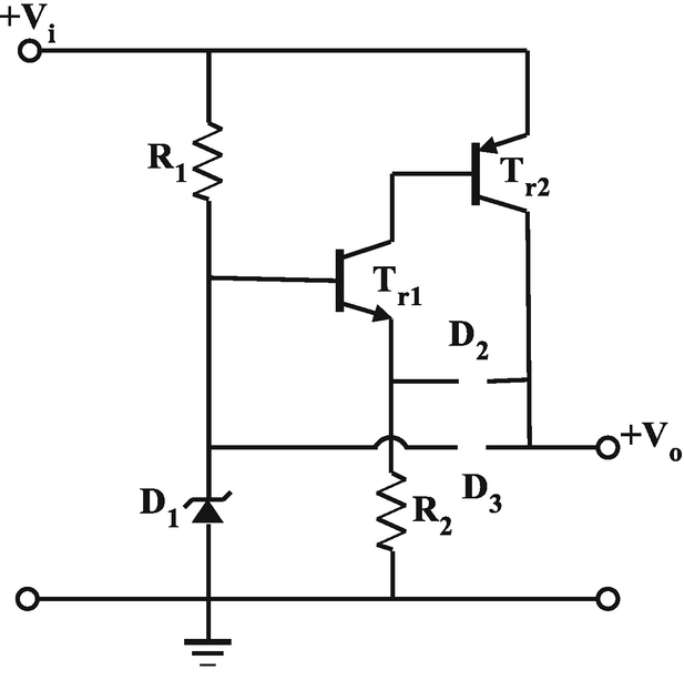
Circuit for Question 8
.
-
9.
Explain the operation of the regulator circuit shown in Fig. 10.67, describing the circuit corrective action for unwanted increases or decreases in the output and giving an indication of the action of capacitor C.
-
10.
Using the circuit shown in Fig. 10.67, design a +16 volt, 1.2 A regulator that is driven by an unregulated supply having 2 volt peak-peak input ripple. Use a 20 volt transformer and a bridge rectifier to provide the unregulated input. Assume the power transistor has a gain of 20 and the other transistors have gains of 125. Justify all your design steps.
-
11.
Show how electronic protection can be added to this circuit and describe its operation.
-
12.
Introduce bootstrapping of resistor R3 in the design of problem 10 and describe the effect of this bootstrapping.


Circuit for Question 9
-
13.
Using the circuit shown in Fig. 10.68, design a +16 volt, 1.2 A regulator that is driven by an unregulated supply having 2 volt peak-peak input ripple. Use a 20 volt transformer and a bridge rectifier to provide the unregulated input. Assume the power transistor has a gain of 20 and the other transistors have gains of 125. Justify all your design steps
Fig. 10.68 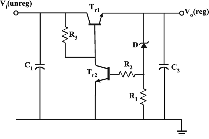
Circuit for Question 13
.

-
14.
Design a regulated supply using the basic topology in Fig. 10.69 rated at 10 volts and 150 mA. Power for the regulator must come from an unregulated supply using a half-wave bridge rectifier and a 12 volt transformer having a ripple voltage of 1.5 volts peak-to-peak at maximum load current. Use a pass transistor with current gain of 150. Include short-circuit protection in your design
Fig. 10.69 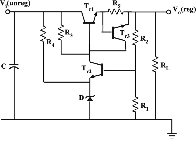
Circuit for Question 14
.

-
15.
Using the circuit shown in Fig. 10.70, design a +20 volt, 1.5 A regulator that is driven by an unregulated supply having 2.5 volt peak-peak input ripple. Use a 30 volt transformer and a full-wave rectifier to provide the unregulated input. Assume the power transistor has a gain of 50 and the other transistor has a gain of 150. Justify all design steps
Fig. 10.70 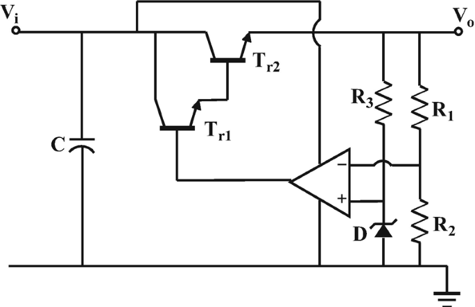
Circuit for Question 15
.

-
16.
Discuss the manner in which output voltage variation can be introduced in this circuit.
-
17.
Design a 9 volt regulator using the 7809 regulator IC.
-
18.
Design a single transistor regulator to power a small radio from the mains supply. The required voltage is 6 volts and the maximum current demand is 50 mA.
-
19.
How can a constant current diode be used to improve the performance of a regulated power supply?
-
20.
Indicate other methods of improving the performance of a regulator.
-
21.
Design a +12 V regulated supply using regulator IC from the 7800 series.
-
22.
Design a ±15 V regulated bipolar supply using regulator ICs from 7800 and 7900 series.
-
23.
Using the circuit of Fig. 10.51, design a variable voltage regulated supply that can deliver 0–9 V at 100 mA.
-
24.
Design a variable voltage bench power supply using a Darlington pair and the topology of Fig. 10.71.
-
25.
Outline the operation of a switch-mode buck regulator.

Circuit for Question 24
Rights and permissions
Copyright information
© 2021 Springer Nature Switzerland AG
About this chapter

Cite this chapter
Gift, S.J.G., Maundy, B. (2021). Power Supplies. In: Electronic Circuit Design and Application. Springer, Cham. https://doi.org/10.1007/978-3-030-46989-4_10
Download citation
DOI: https://doi.org/10.1007/978-3-030-46989-4_10
Published:
Publisher Name: Springer, Cham
Print ISBN: 978-3-030-46988-7
Online ISBN: 978-3-030-46989-4
eBook Packages: EngineeringEngineering (R0)